Who doesn't know the problem
to generate a small voltage (e.g. 5V) out of a high one? Sine several years
you go to the lab and find.... Switchmode regulators with integrated switches.....
But none with more than 3 or 5 Ampere in general. If you find one, it's
not easiely to apply and can't be buyed @ the next corner.
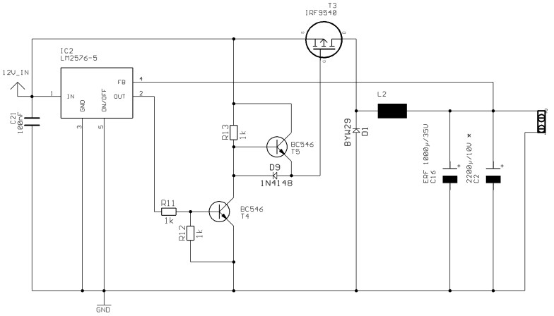
Why not try to "enhance" a Simpleswitcher
(National Semiconductors)?
The LM2575 works a regulator only
and don't deliver any current to the load.
If the regulator switches "ON",
you find a voltage at the output of it. This makes T4 switching on also.
The collector of T4 now is nearly
GND and also the Gate of FET T3. This FET switches on (it's a P-FET!)
For T3 you can take everything
what's called Power P-FET with low RDSON, a IRF9540 is a good choice.
(The lower the higher the price
:-)
The "invention" of this circuit
is the Gate turn off of T3.
In ON State, The Gate of T3 has
nearly GND potential, D9 conducts and T5 is off.
If now the Regulator switch it's
output OFF, then the Base of T4 is pulled low by R12 and no currents flow
through T4.
Also the cathode of D9 is connected
to Vcc via R13. The stored energy in the Gate capacity of T3 lets now pull
T5's emiter lower then the base. Whats happens if the Base of a NPN transistor
has higher voltage than the emiter? It conducts ! Now, T3's gate is directly
connected to the source via T5 and the gate capacity can be discharged
very fast.
This happens several times faster
than if you only had R13 to discharge the gate capacity !
Where you get your losses now?
First, watch Diode D1. If the switch
(T3) is opened (high impedance), this diode conducts and carray ALL the
current!
So, lets have a duty cycle of 0.5
then the loss in D1 are: 0.5*Vd*Ia (Vd=voltage drop @ D1 and Ia=output
current).
E.g.: Ia=8A, Vd=1V -> 0.5*8A*1V=4W
of loss !!!!! Therefore, take a (Shottky) Diode with lower Vd !
Second, the FET has losses:
1. In the full conduct state the
RDSON. The IRF has a typical RDSON of 0.2 Ohm. If you have a duty cycle
of 0.5 again and 8 A of output current, then the losses are: 0.5*8A*8A*0.2
Ohm =~6.4W of loss. To minimize this losses, take a FET with lower RDSON
(higher cost).
2. If the FET is turned on and
off, it "walks" through a state of gate-voltage dependent resistance.
In the Turn-On moment, this losses
are smaller than in the turn-Off moment (because the current is smaller
if the FET turns on than it is if it turns off, the current in a coil grow
linear!)
Therefore, the "trick" with T5
was made to minimize this time and therefore also the losses.
Calculate this losses is a bit
difficult, so it isn't explained here.... But believe it (or try it by
remove T5 and D9:-)
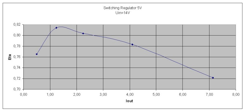
What can you get out of this piece of electronics?
I tested this arrangement up to
8 A (look at the diagramm), but if you use other FET's and diodes, you
will get MORE!
But with increasing current, the
losses in D1 will grow rapidly so you have to replace it with a MOSFET,
but this is a synchronus rectified SMPS and not discussed here :-)
But this circuit has an disadvantage:
It's not protected against overcurrent,
so you should use a Fuse!
If you find a circuit to short
protect it and get minimal losses, please mail me !
Also you should read the LM2575 Datasheet and the Application notes !
Something to the used parts:
For the LM2575 you can also use
a LM2576.
Diode D9 can be any fast Diode
with enough reverse voltage and low forward voltage (also you can use a
shottky Diode).
Best to get and mount seems a BYW29
in TO220 package.
Be warned !!!! A simple 1N4007
wouldn't work!
The output capacitor should be a
special LOW-ESR type (E.G. out of a PC- Power supply on the secondary site,
Look at the voltage rating !)
FAQ:
Question:
You can also us a SG3525 or aequivalent?
Answer:
Yes, but in the LM2575 is all you
need ! Only a small amount of external parts are needed and you can save
board size!
Question:
Can I also take a N-FET, they have
a lower RDSON?
Answer:
NO! To turn on a N-FET you need
a higher voltage @ the gate. But where to get it?
Question:
Why do you use the LM2576?
Answer:
This part I found in higher count
in my drawer :-) But you can also take a LM2575. It doesn't ,matter.